


2.77 Week 2
- Feb 19, 2017
- 3 min read
Week 2 started with a snow day. Classes were canceled, but very quickly, the pace picked up. This week contained a good mix of building, and brainstorming. Read on to find out.
PUPS #2: EXACT CONSTRAINT DESIGN
This week we sought to understand how an exact constraint works physically and virtually.
A FRDPARRC chart is used to see the big picture and have a thorough analysis before actually making the part (Danny's comments are in green):

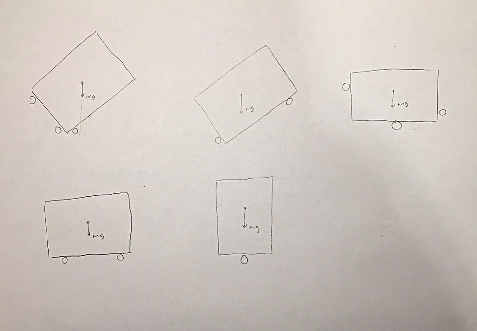
The EC system is modeled to predict the forces on the constraining points as a function of where the fores are applied to the object:


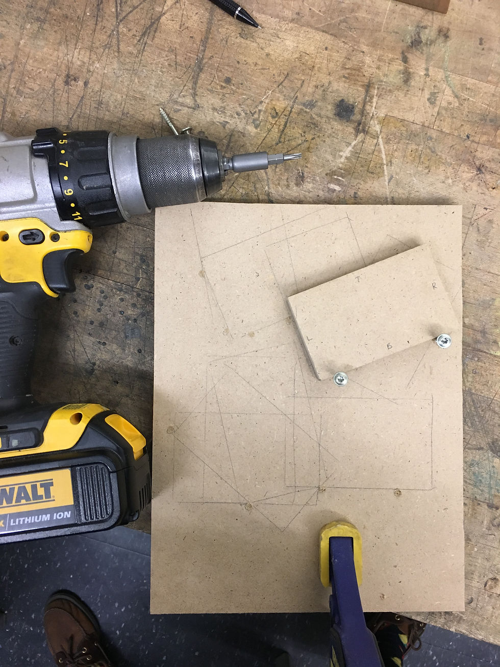
The planar EC system is made out of plywood. Due to a lack of standard dowel pins, I had to adjust the design, and use wood screws instead. I placed the wood screws in meaningful locations on the plywood board to create different constraint scenarios. Please watch the video below for the finished prototype, and a run-down on how to play it!
HARDWARE: CONTROL OF STEPPER MOTOR
Connected the NEMA 17 stepper motor to a DRV8825, a V3.00 CNC shield, and an Arduino Uno. Watch the stepper motor run in this video!
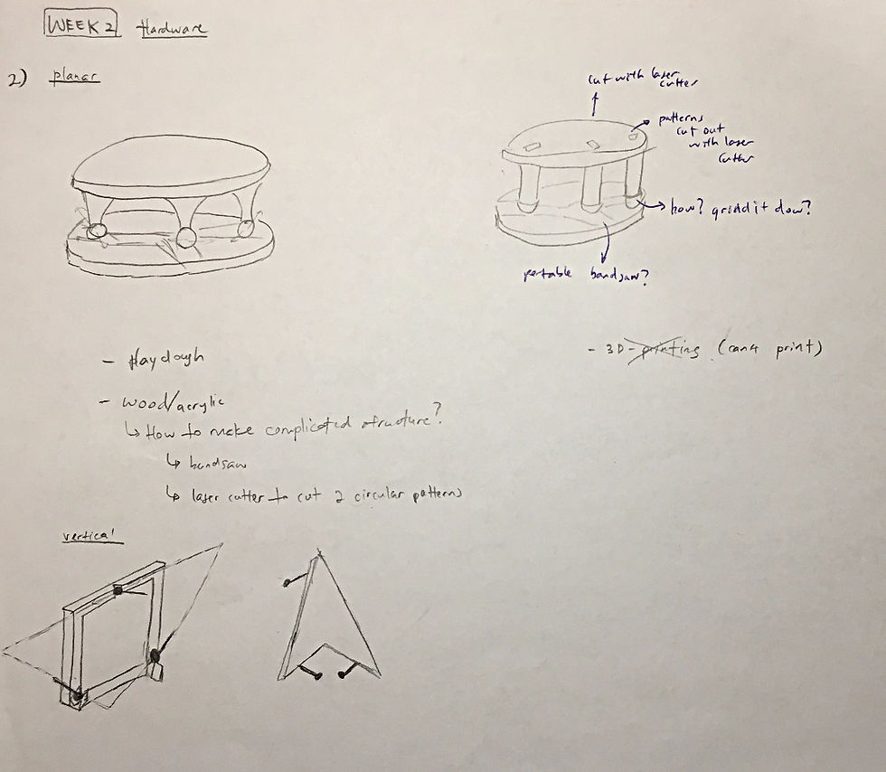
HARDWARE: EXACT PLANAR CONSTRAINT DESIGN AND BUILD
Brainstormed for ideas
Found a 3-wheeled injection molded part in my microwave, and scavenged a piece of foam from the IDC. First, I marked out the locations of the wheels on the foam, and used a circular bowl to make rough markings around the 3 wheel locations.

Next, I cut out the foam on a bandsaw, and drilled out some foam at the wheel locations. I tested the fit with the wheels, and it turned out pretty good. There is only ~3mm play.

Next, I created the top coupling using the extra foam, and secured the wheeled part to the foam using wood screws.

To test the part further, I attached a laser point onto the top coupling, and measured the horizontal and vertical difference at a 3.3m distance.
The results are summarized here:

A few things that I noted were:
(i) The laser pointer is taped too loosely. It moves when pressed. This contributes to a larger deviation in the reading. This error cannot be attributed to the kinematic coupling itself, and can be prevented by fixing the laser pointer to the top coupling. Nevertheless, using Cosine Rule, the angular error is only 1 degree. The kinematic coupling is relatively repeatable, but will need work to make it more repeatable.
(ii) I moved the bottom coupling instead of the top. This is not the most accurate way to simulate the motion.
BRAINWARE: LINEAR MOTION SYSTEM DESIGN
1) Deterministic Design of Simple "Precision" Linear Motion System


Error Apportionment Spreadsheet (Linear Motion Axis) is used to calculate the remaining critical dimensions of the system, given chosen dimensions. Details and calculations of structural and machine elements analysis have been added to Week 3's blog post. The Error Apportionment Spreadsheet have also been updated in Week 3's blog post.
GEEK & SEEK: DUAL FLUSH TOILETS
In the Global Manufacturing seminar, Harald Quintus Bosz, CTO of Cooper Perkins, came to talk to us . The company is focused on technology development. In other words, they validate new technology and prove their feasibility in reality. One product in particular piqued my curiosity: the automatic toilet flusher that is able to control water use. Every now and then, I come across toilet flushers that have only a single flush volume. I wonder what is the mechanism behind dual-flush toilet kits.
In the older revisions of toilet flushers, water is dispensed when the user pushes the flush button. The flush button is connected to a flush valve that dispenses water. Once the water is depleted, the refill process is controlled by tank fill valves. The figure below shows a float valve. When the fluid level drops, the float also lowers, thereby opening the valve and letting water enter the tank. The valve is shut once the tank is full, and the float upright.

This is a simple explanation of the flushing system. Often, the siphon flush system is used. Siphon flush makes use of a s-shape trapway that allows waste to be removed quickly, and the tank fill valve for refilling. This is a good video by Discovery Channel explaining the siphon flush.
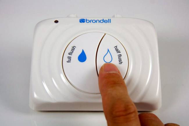
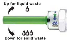
Dual-flush systems first appeared in Australia, and was popularized by toilet manufacturer Caroma. Modern dual flush toilets use 3L to flush liquid waste and 6L to flush solid waste. The type of flush is controlled by buttons, which in turn determines whether the air hole is covered or uncovered (see figures below). By having the air hole uncovered, only half the tank will be emptied.

There are many efficiency advantages to the dual-flush system. For one, it uses a large trapway, and a wash-down flushing design that depressurizes the trapway to enable more energy efficient waste removal as compared to the siphon flush system.
Comments