


CAD & Drawings
- May 21, 2017
- 1 min read
With my calculations more or less in the bag, I moved quickly to CAD. I painstakingly measured every component on my Bill of Material, taking note of every critical dimension. I then checked what I had measured with the manufacturers’ specifications making sure there is no discrepancy.

I also planned out how I will be using the scrap Baltic Birch plywood that I had found.
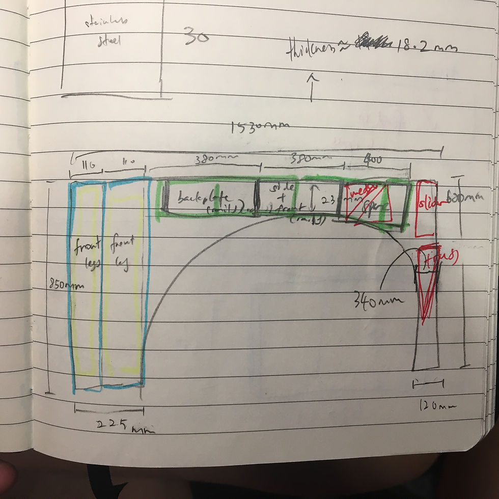
Next, I quickly created CAD models for every single component, and assembled them into one file. I wanted to see if everything will fit. By looking at the interferences, I made further adjustments to my design. The crucial thing for me is spec-ing out the height of my assembly. Since I had decided to do away with one long rail in place of "legs," this means that I had to carefully calculate the amount of rails I will needed. Rails that are too short will meant that I will have to cut my leadscrew. Rails that are too long will meant that my leadscrew will not reach the top bearings. CAD was tremendously useful in that regard. I was able to constrain the amount of leadscrew and the amount of motor shaft to 7.3mm, and adjust everything else from there.

Here are the complete CAD models & part drawings
Comments