


Building the Table
- May 21, 2017
- 4 min read
Most of the woodworking and machining was done at the Hobby Shop. There is just such an amazing collection of machines and hand tools available. For this project, my favorite machine is the Saw-Stop table saw. It is safe, and incredibly accurate doing straight cuts on wood. Here is a video of the machine's inventor putting his finger into the blade, and not having a single scratch. I think it's amazing.
In order to be efficient at building, I created a sequence of cuts for each subassembly. The two main subassemblies are:
(i) rails+truss+leadscrew+bearings
(ii) base+motor.
Sequence of Build
A. Rails + Slider
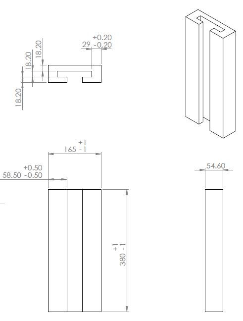

The rails is my Most Critical Module. I had to make them line up almost perfectly, in order to not have too much table rattle (i.e. overshoot the geometric errors I had apportioned for my vertical axis).
Using the table saw, I cut my Birch plywood into the back plate, the guiding strips, and the keeper rails. It turned out very precise.
Using the table saw, and a cross-cut jig, I got my slider down to dimension.
Hand-sanded slider and rails down to P320. Slider moved smoothly
Before gluing the back plate to the guiding strips, I inserted thin plastic sheets measuring 0.13mm in thickness between slider and the sides of the guiding strips.
The next morning, I installed keeper rails by gluing them down. Taking note to add a piece of paper 0.2mm thick for clearance between the rails and my slider.

B. Truss + Slider

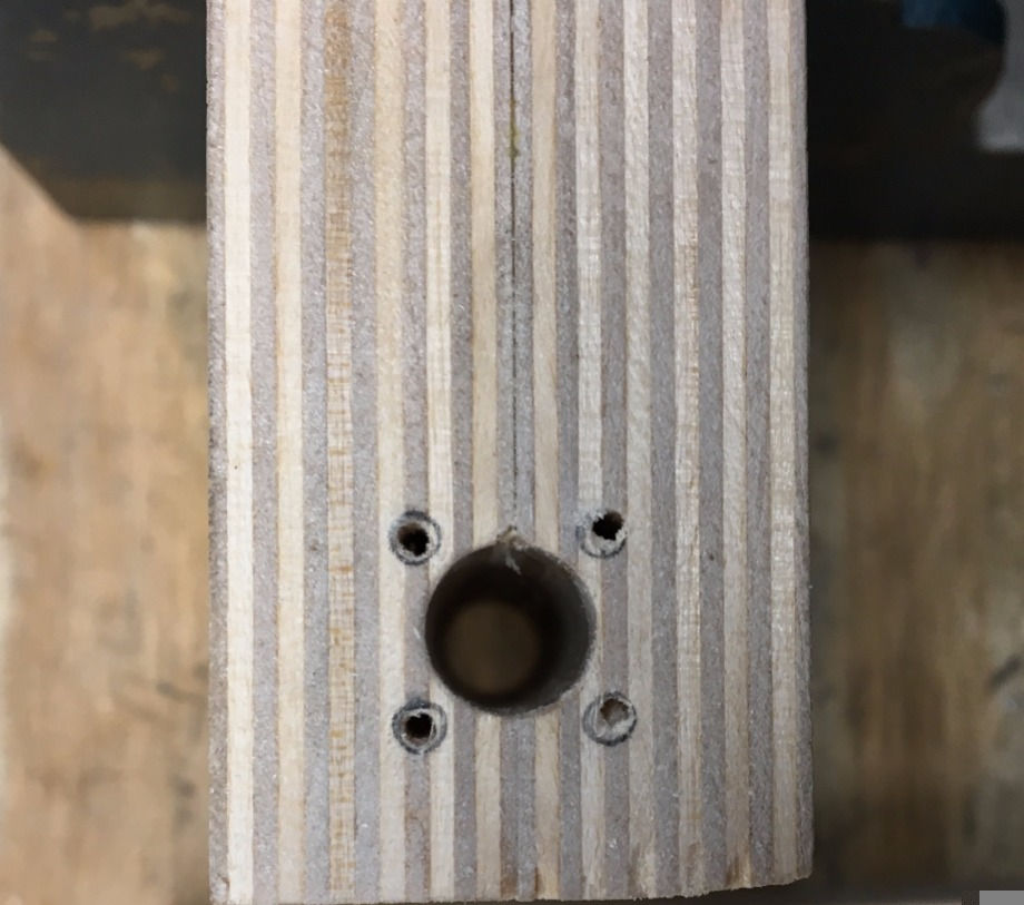
Glued two pieces of rectangular Birch plywood measuring 240mm by 100mm together to get overall thickness of 36.4mm
Using the drill press, I created a 10.41mm clearance hole for the leadscrew nut, and four 2mm pilot holes for wood screws to secure the nut. The length of the clearance hole is 100mm, a specially chosen dimension. If it were any larger, the 11mm drill bit will not be able go all the way through my part.
Once the glue dried up, I cut the truss to dimension using the bandsaw
I pre-drilled four pilot holes on my slider, and glued it to my truss
Attached leadscrew nut onto truss
Using four 1/4” x 1.5" wood screws, I firmly secured the slider to the truss. However, the quality of screws that I used was terrible. I could not get it all the way in without shearing the threads. In the end, I just took a file to it, and ran it on the belt sander to make the side flush.
Overall, I am very satisfied with how the slider turned out. It slides in my rails smoothly with very little rattle. Notice how snugly my slider fits into the rails *grin*

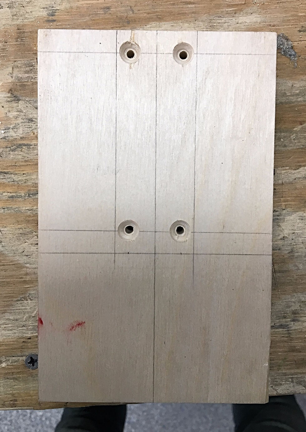
C. Top bearing plate
Pre-drilled two pilot holes for M5 wood screws
Aligned top bearing plate with respect to datum (i.e. back of rails)
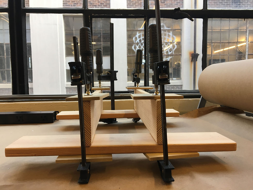
Glued top bearing plate to the rails
I should have installed the bearing before glueing. This would have saved me the time turning a screwdriver with hardly any room to turn. Nevertheless, I still managed to secure the bearings to top bearing plate.

D. Base

Cut 2m long plank into side-facing and front-facing legs
Pre-drilled 8.5mm holes on side-facing legs at four locations
Glued legs together
Drilled deeper holes
Use four ½” x 1.5" wood screws to secure legs
E. Motor Mount + Spacers
From the dimensions of my motor, I designed a motor mount to be placed at a height, in between the two front-facing legs.
I cut out the 1/8" acrylic mount using the Epilog laser cutter at IDC.
With M3 screws that I found in Makerworks, I tested to make sure everything fits.
At the same time, I had created small spacers to bring my motor mount to the same height as my motor
Glued the motor mounts to the base, and attached the motor mount using two 1/4" wood screws
F. Bottom bearing plate
Like the top bearing plate, I pre-drilled two pilot holes for two M5 screws. I also drilled a clearance hole for the leadscrew itself.
Glued bottom bearing plate to rails. Completing the rails subassembly.
Misalignment here is a big issue. Despite all the good efforts spent aligning the bearings plates, they are still slightly off. This causes the slider to jam while on the way up. This is because the friction forces between leadscrew nut and leadscrew/slider and rails are higher than the actuation force that my stepper motor can provide.
I readjusted the positions of both top and bottom bearings twice, before I finally got it right.
G. Leadscrew
Milled a step on my ACME leadscrew, to ensure good contact with set screws in coupling
H. Assembly of leadscrew and subassemblies
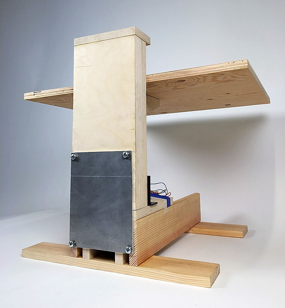
This comes in two phases: steel brackets, and Al backplate. Both serve an important purpose of keeping my rails upright on the base.
I. Steel brackets
Pre-drilled 8.5mm pilot holes on rails and the base
Used two ½” x 1.5" wood screws for each bracket
J. Al backplate
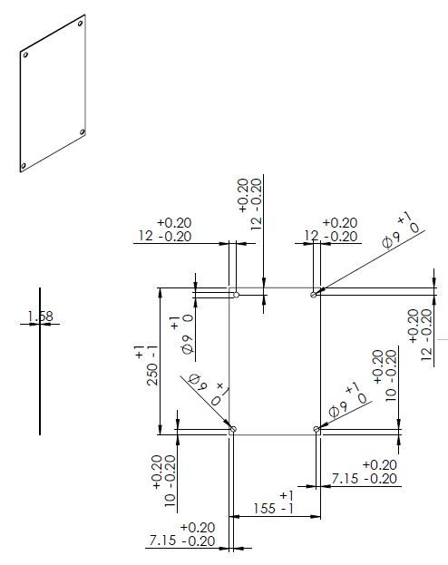
The idea of the Al backplate is to join the two main subassemblies together.
First, I used a hand drill to create pilot holes on both the rails and the base
Using the drill press, I created 9mm clearance hole on Al backplate. That being said, I had to enlarge the holes to 12mm clearance for better alignment with the hand drilled pilot holes.
Using four ½” x 1.5" wood screws with split washers, I was able to secure the two subassemblies together pretty tightly.
K. Table top
Pre-drilled the truss
Counterbored the table top
Used five ½” x 1.5 wood screws in spaced only 30mm apart, to make sure the stress cones overlap.
L. Touch up
Used the Festool Orbital Sander on all surfaces to a nice P320
Filled in some blemishes using Minwax wood filler
Comments