


2.77 Week 3
- Feb 26, 2017
- 5 min read
HARDWARE: LINEAR MOTION SYSTEM
The most exciting part of this week is probably designing and building a linear motion system at the International Design Center (IDC).
I started early on this project, and went around looking for inspirations. I first noticed linear motion systems on TV wall mounts.
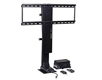
They looked really sophisticated, and it didn't help that their mechanism is enclosed in a black housing that I cannot peer in.
I went online and found a series of YouTube videos about linear motion systems ranging from belt drives to motor-powered leadscrews to vertical carriages that travel on an 80-20.
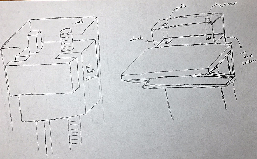
The videos really inspired me. But I weighed my options, and decided that given the time constraint, it might be best to stay simple. I went to the IDC to build a simple linear motion system, closely resembling Professor Slocum's in-class demo.
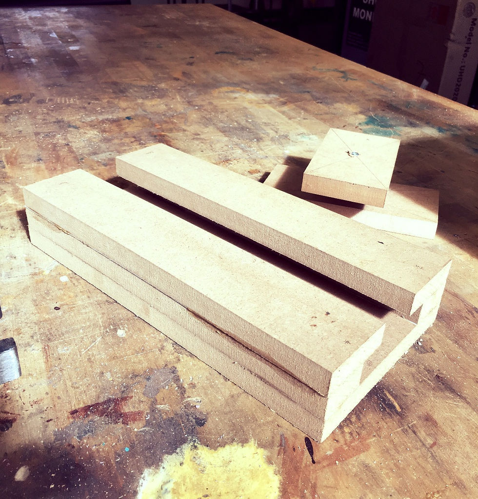
At IDC, I found a piece of MDF measuring 48cm by 32.5cm. I quickly made amendments to my error apportionment spreadsheet, and found the appropriate dimensions for each part:


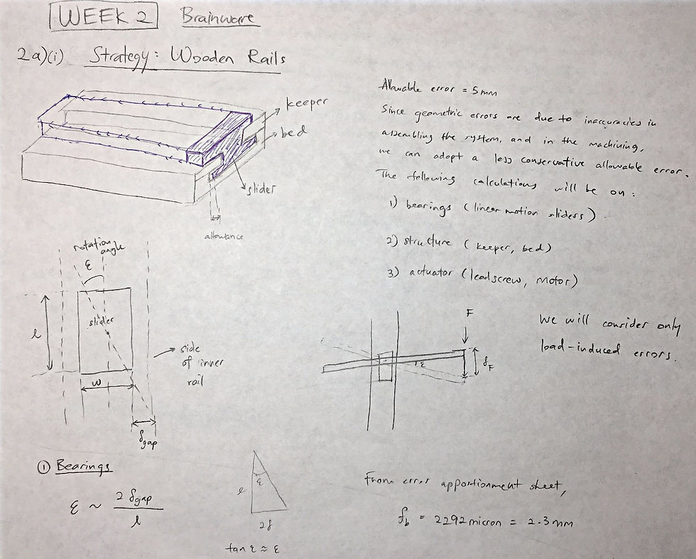
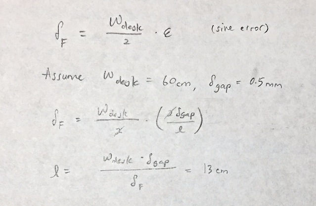
Prior to this, I added more rigor error calculations to the Brainware of Week 2:


After dimensioning the MDF, I cut out the pieces on a bandsaw, using the saw fence to get straight cuts.

Knowing that wood slippage is a common source of error. I used a nail gun to insert a series of nails onto each piece of MDF. I clipped off the head to create sharp tips, which serve to increase friction and grip to prevent slippage.

Finally, I applied wood glue to each MDF surface, and added some paper for height clearance. I clamped the wood pieces together pretty tightly. But I later read that it was not a good idea to clamp too hard. It will squeeze the wood glue out, causing a weaker bond. Nevertheless, the linear axis system turned out pretty well. The error is little bigger than I would have hoped (see analysis in error apportionment spreadsheet), but I have a much better idea what to do moving forward.
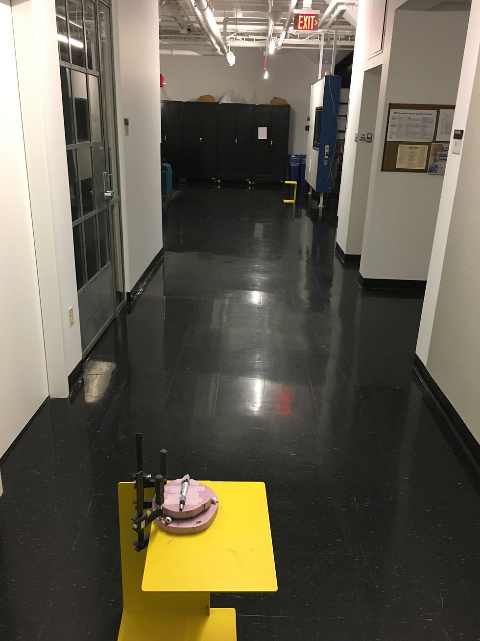
The first video is an introduction of the linear motion system:
The second video shows some preliminary tests:
Repeatability tests were also conducted. It shows that there is still some wiggle room. The gap clearance is 2.5mm. An improvement will be to build a wider slider to minimize the clearance.
HARDWARE: KINEMATIC COUPLING
After designing and making the kinematic coupling last week, I received some feedback that my design needs improvement:
1. The coupling should only have 6 points of contact.
2. The repeatability test should only include me lifting the top coupling, and putting it back.
This week I cut out some V-grooves in the bottom coupling to ensure 6 points of contact, and added rubber bands near the wheels to reduce play.

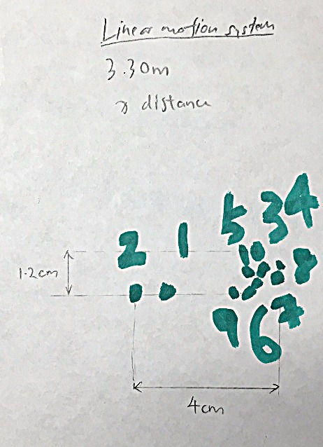
I repeated the test at 3.30m and at 20.50m by securing the bottom coupling, and only removing the top coupling. The results are very encouraging. At the 20.50m range, all of the points fell within 1.5cm of each other.
BRAINWARE: STRATEGY
This week's Brainware centers around strategy creation for the height adjustable table.
I started the activity by brainstorming a wide range of ideas, and incorporating designs I found online into my specific context:


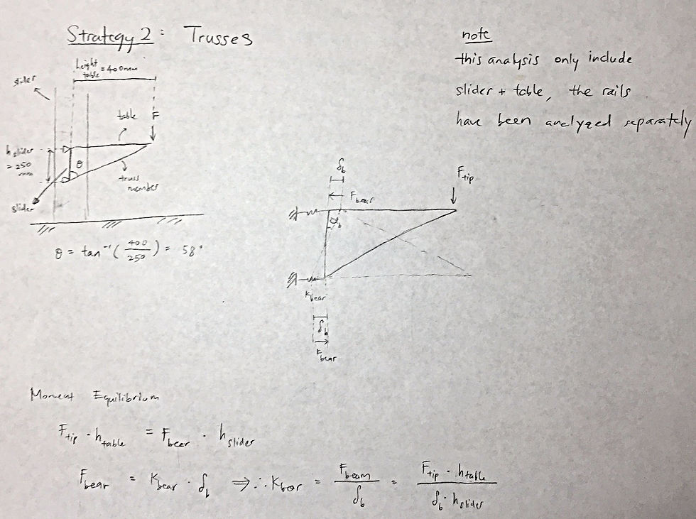
Out of all the preliminary strategies, I decided to analyze two main ones:


GEEK & SEEK: THE SMITH MACHINE
This week I was on the lookout for inspirations to build my linear motion system. I came across this smith machine in the gym:

It has vertical carriages running on steel rails at a near-vertical angle. There are also many slots along the vertical rails, making the Smith machine safer than using a barbell.
When I was on using the machine, I realized that I am able to do heavier weights than I normally can with free weights. This intrigued me, and I did some research.
Apparently, the vertical rails help to provide stability to the user, making the lift easier. Additionally, the Smith machine has built in counterweights, which reduces the lift from the get-go.
As a result, there are many critics of the Smith machine. One main complain is that it inhibits proper muscle development. For instance, when you are doing a free-weight bench press, you activate your rotator cuffs to stabilize the bar. So after using the Smith machine, our rotator cuffs might not be prepared for the stabilization required if we ever switch to free weights. This makes us more prone to injuries.
PUPS #3: MACHINE DESIGN
Prompt: Think of the machine you want to design, build and own as the term project in this class.
1. State the problem to be solved, what else exists, and why you think you should design a new machine (even if just for fun). (1 pt)
I often find myself slouched over my desk. There is no flexibility to adjust the table, in order to write/type while standing. The fact that I have high myopia did not help with my already poor posture. I want to have the choice to adjust a table’s height to its appropriate level for writing/typing. If possible, this table can slant at an angle, and still allow me to write/type/paint.
Currently, there are two main types of tables out in the market. First, we have the expensive workdesk, which is usually a standalone, self-supporting structure. An example is the NextDesk. It is an electronically controlled work desk that has stable motion, and up to 200 height positions. The retail price is an exorbitant $1,500.

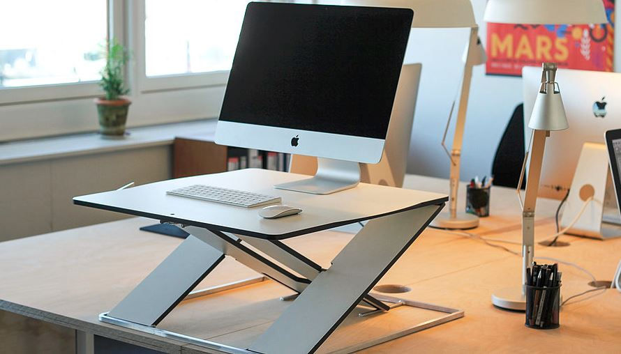
Second, we have a smaller desk that you can put on top of your existing table top. An example is Oploft. It can be stored easily, and operates on a sliding bearing mechanism. However, it can only be manually controlled, and cost $500.
This motivates me to build a cheap, sturdy height adjustable desk. Of course, it is a great excuse for me to practice machine design.
2. State the Functional Requirements and specifications for your machine, with the understanding that other than three stepper motors and the Arduino control board and stepper motor drivers, each student has to scrounge up their own materials. (1 pt)
Functional requirements and specifications can be found in FRDPARRC table
3. Embody the FRs in a FRDPARRC table for your machine (where a lot of the entries of course will be blank, but as your design progresses you can fill them in). (1 pt).
4. What are the forces the machine has to withstand? (1 pt) a. If a cutting machine, think of the power of a similar machine, the speed of the spindle, and diameter of the tool to estimate forces…
Point loads: My elbows on the table when I lean on it. Writing force
Distributed loads: Textbooks, laptop, mouse
Note
I had overlooked the syllabus change, and was rushing out the additional sections of Brainware for Week 3. But I did a lot of thinking of my project, and came up with some exciting ideas. I will incorporate the information into this blogpost /or the next one. And I will complete the remaining sections of PUPS 3 by the end of this weekend.
Comments