


2.77 Week 4
- Mar 5, 2017
- 3 min read
I cannot believe this is only week 4. It feels as though I've done more building and thinking on my two feet in this one month than the past year. Some time this week, I decided to read the Ethics chapter for fun, and it was a fantastic decision. I really appreciate the well-placed humor in that chapter. If anything, it helped me commit to memory some very important tenets of professionalism.
This week I caught up with some work from last week, and finished the assigned PUPS, Hardware, Software, and Geek & Seek.
PUPS #3: MACHINE DESIGN SPECIFICATION
Last week, we looked at deterministic design of the height adjustable table. I stopped at Q4.
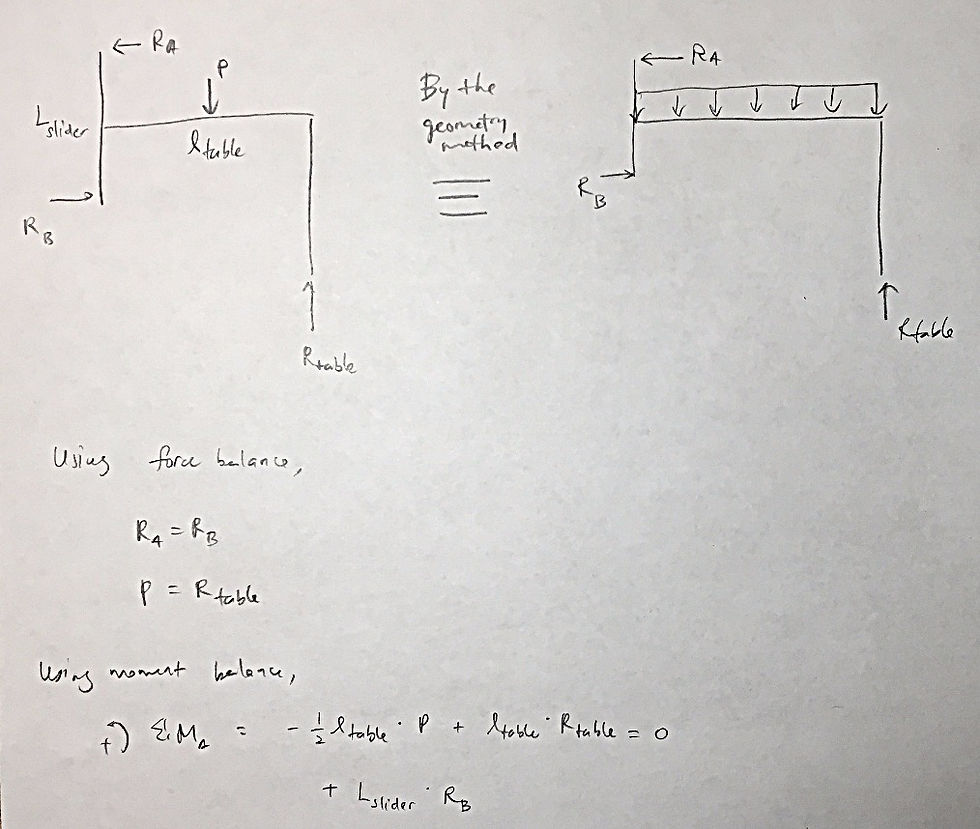
4. What are the forces the machine has to withstand? (1 pt)

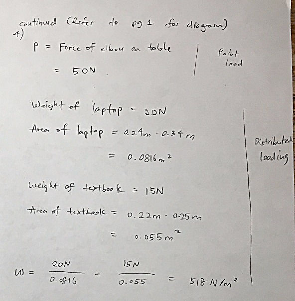
5. Given the desired accuracy of the machine, what is the required stiffness? (1 pt)

6. Assume the structural loop length of your machine is three times the sum of the distances each axis must travel, to get a feel for the structural loop: (2 pts) a. What is the size of a cantilever beam (tube cross section) whose length is the length of the structural loop?

7. Sketch stick figures for different strategies you now envision for solving the problem. (1 pt)


a. Use the basic starting FRDPARRC and enter more detail for each strategy
b. Apply Error Apportionment for different strategies
Please find the FRDPARRC table here.
Please find the error apporptionment spreadsheets here.
8. Create geometric error budgets for “top” strategies. (2 pts)
Will be included next week. Have to clarify some calculations during office hours this week.
BRAINWARE (WEEK 3)
2c) Use error apportionment spreadsheet
2d) Model 1st order loads, stiffness requirements.
See Q7 of PUPS #3 above.
PUPS #4: KINEMATIC COUPLING DESIGN
Your machine will likely have to have things easily attachable/detachable
1. Design a 3D kinematic coupling (for example that could be used for example as a tool or fixturing holder on your machine). (2 pts) a. You cannot just “print it”: you have to make it!
2. Build and test it: (6 pts) a. Stiffness b. Repeatability c. Accuracy
3. Compare tests to predictions (close design loop). (2 pts). a. How would you change the design and update the spreadsheet?
See "Hardware: Kinematic Coupling" in Week 3 blogpost, and "Brainware (Week 4)" below.
Updated kinematic coupling error spreadsheet can be found here.
BRAINWARE (WEEK 4)
a) THREE GROOVE KINEMATIC COUPLING
Last week, I left out the raw results of my repeatability and accuracy tests. I repeated the test at 3.30m and at 20.50m by securing the bottom coupling, and only removing the top coupling. The results are very encouraging. At the 20.50m range, all of the points fell within 0.6cm of each other.


Please find the kinematic coupling error spreadsheet here. A summary of the allowable errors at the points of contact are as follows:

b) PICK BEST STRATEGY
I am leaning towards a combination of the two designs. Further analysis will be done soon.

HARDWARE
a) LINEAR MOTION SYSTEM
Completed last week. Refer to "Hardware: Linear Motion System" in Week 3's blog post.
b) KINEMATIC COUPLING
Completed last week. Refer to "Hardware: Kinematic Coupling" in Week 3's blog post.
SEEK & GEEK: ASSISTIVE TECHNOLOGY HACKATHON
This Saturday I together with four other friends participated in the Assistive Technology Hackathon (ATHack). The goal is the build a motorized camera mount and a camera user interface that can be controlled simply by using one's foot.
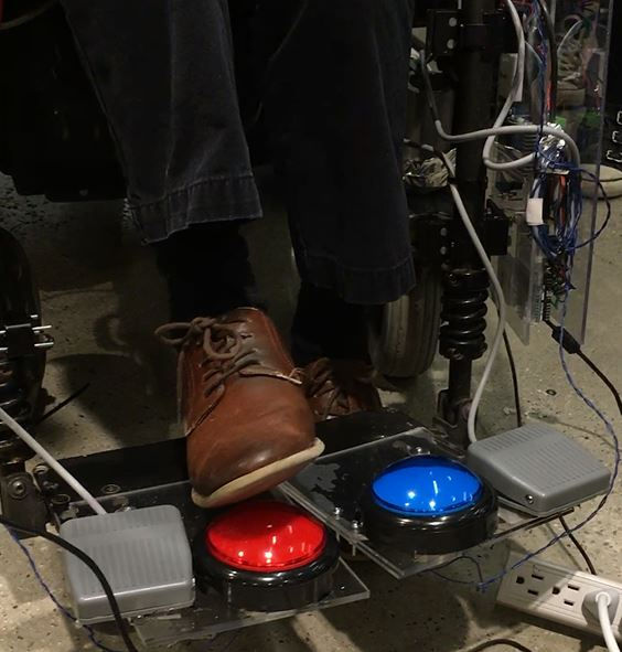
The following picture shows the physical mechanism that we put in place to allow the camera to actuate up and down:

The first issue we had to deal with is how to actuate the leadscrew. There can be two ways. First, fix the leadscrew, rotate the brackets to move the camera up. This means that camera cannot be facing the same direction all the time. Second, we can fix the brackets, and rotate the leadscrew. This will allow the camera to be able to move independently of the rotation of the leadscrew.
After some research, and we designed the following bracket using Solidworks:

In this design, a threaded nut is fixed in position, and the leadscrew will rotate concentric to the nut. The bracket itself is not free to rotate. It is fixed in position by nuts, and by a long aluminum guide running through the square hole on the right. The pitch on the leadscrew is chosen to be a low value to provide enough torque to lift the camera.
You can watch our live demo here:
Comments