


2.77 Week 5
- Mar 12, 2017
- 4 min read
Week 5 is a very eventful week. Flew out of town for a couple of days, and got back in time to start designing, and writing this blogpost.
PUPS #3 (UPDATES)
After obtaining some peer reviews, and comments during recitation, I decided to redo Q6 in PUPS #3.
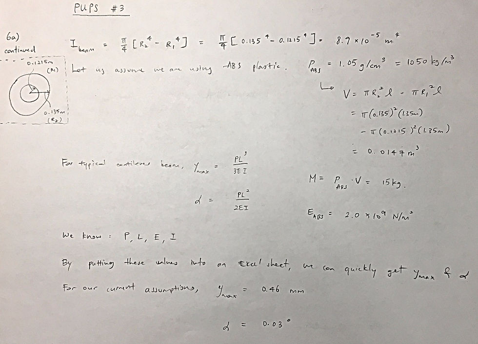
Q6 Assume the structural loop length of your machine is three times the sum of the distances each axis must travel, to get a feel for the structural loop: (2 pts)a. What is the size of a cantilever beam (tube cross section) whose length is the length of the structural loop?i. State your assumptions on proportions.ii. Assume tube outer dimension is 1/5 the length, and wall thickness 1/20 the diameter.
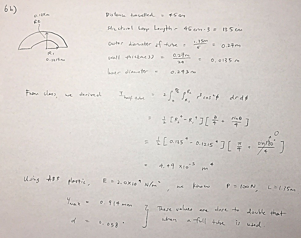
b. What is the size of a C-shaped (curved beam 180 degree segment) (tube cross section) whose length is the length of the structural loop?i. State your assumptions on proportions.ii. Assume tube outer dimension is 1/5 the length, and wall thickness 1/20 the diameter.
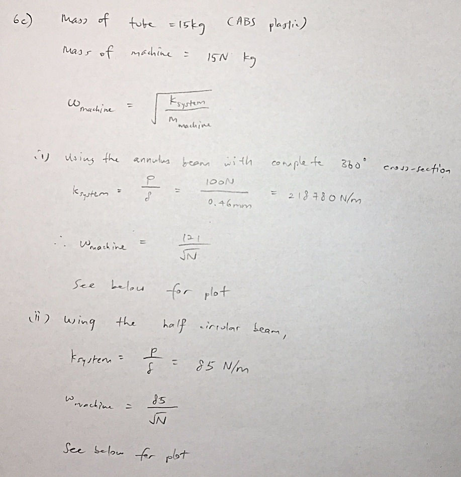
c. If the mass of the machine is N x the mass of the tube, what is a first order estimate of the natural frequency of your machine as a function of N (plot it).

I was curious about the intuition behind moment of inertia. Turns out there are two different moments of inertia:
Area
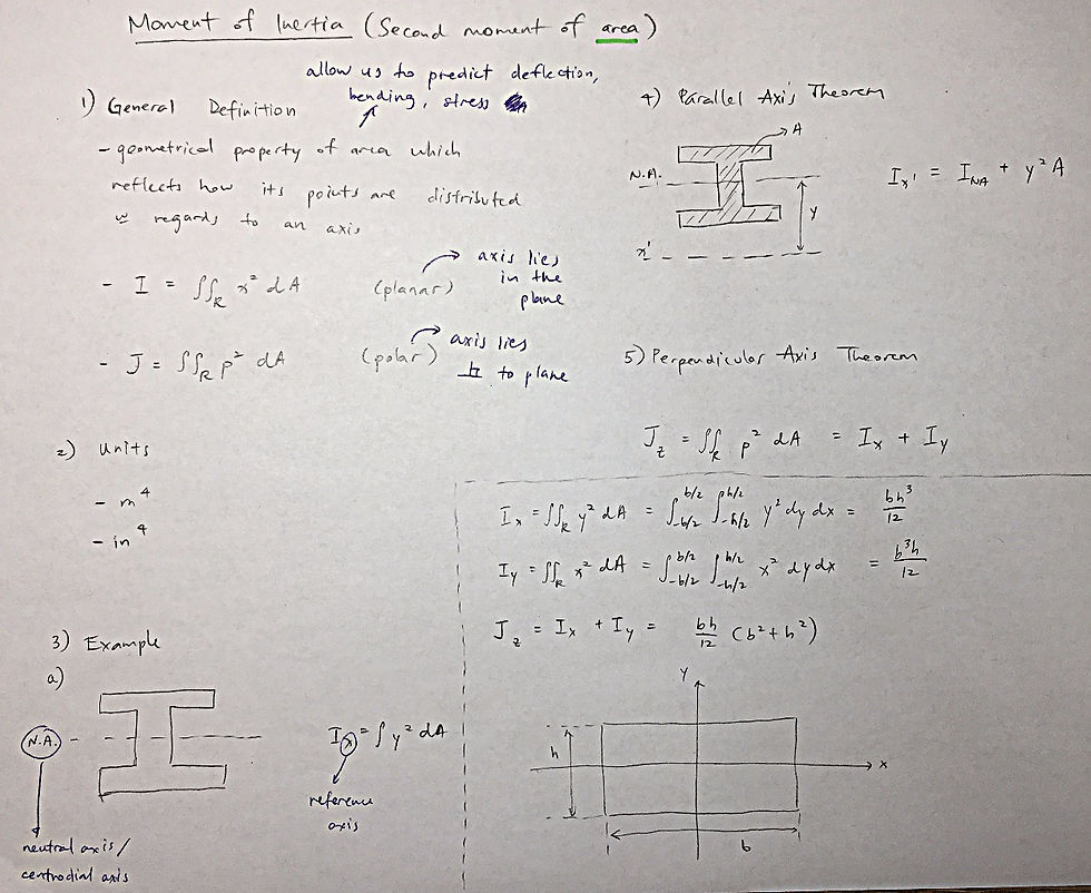

Mass

BRAINWARE WEEK 3 (UPDATES)
Just like PUPS #3, I decided to go into greater detail in my analysis of my two strategies. Danny's comments are in orange. Thomas' comments are in green.
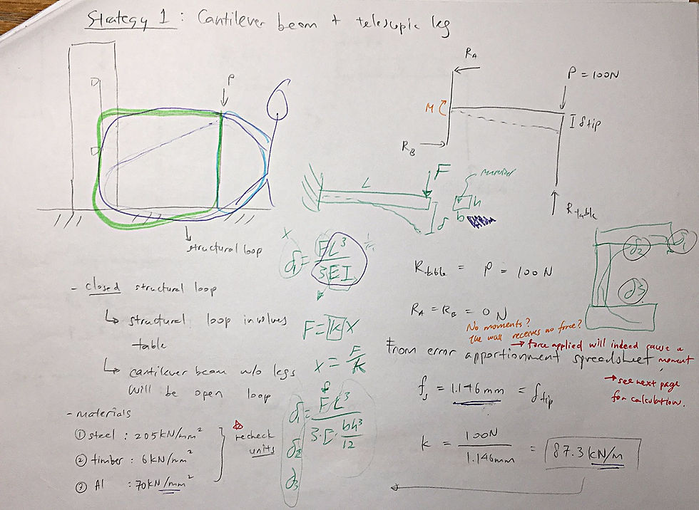
(1) Cantilever beam + telescopic legs

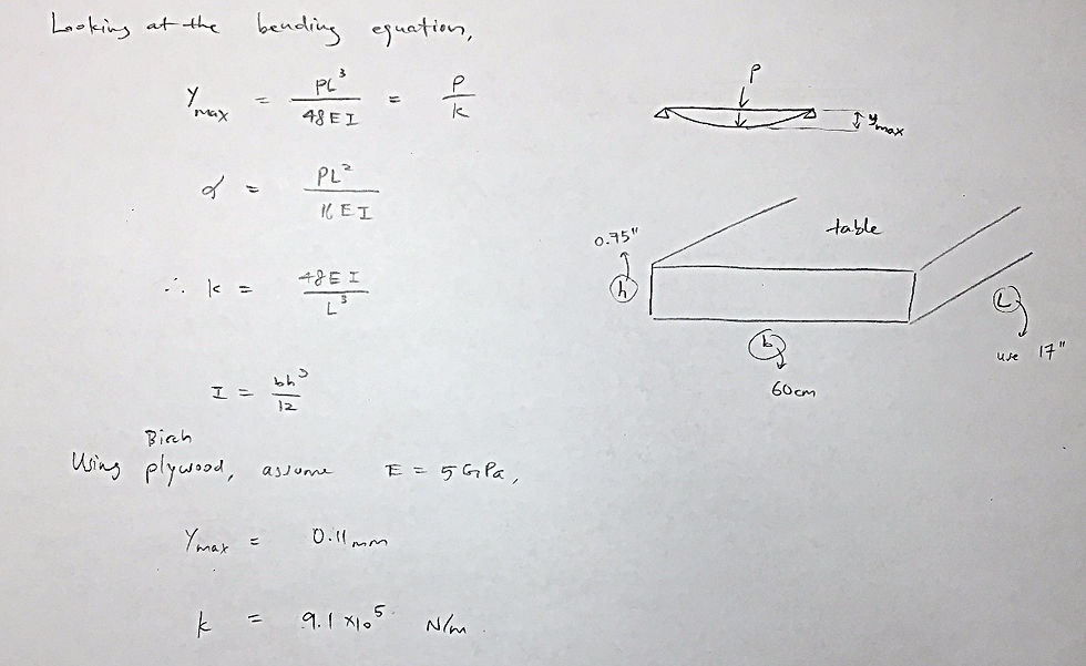
I also created this error budget to analyze my forces, moments, deflections, and stresses.
(2) Truss


I also created this error budget to analyze my forces, moments, deflections, and stresses.
BRAINWARE WEEK 4 (UPDATES)
Previously, I have decided to use a leadscrew to actuate my table vertically. The first step will be to size my leadscrew to determine the diameter and pitch. For a load of 100N, and relevant NEMA 17 stepper motor specs, calculations were done in this spreadsheet.

The sizes of a 10mm leadscrew, and a 8mm leadscrew are drawn in here:

The final sizing shows that a leadscrew of 8mm diameter, and 4mm pitch is likely to be most suitable.
BRAINWARE WEEK 5
Design Iteration #2
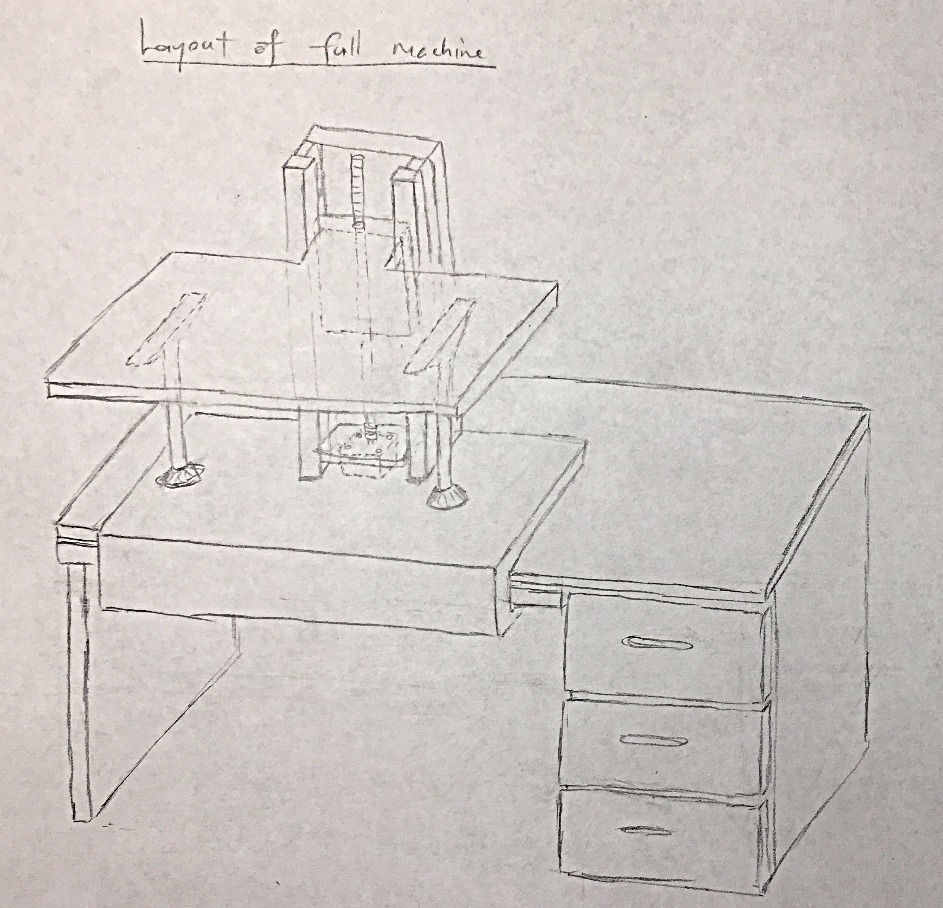
My table will be mounted to a linear axis system. The actuation will be done by a NEMA 17 stepper motor coupled to a 8mm leadscrew with 4mm pitch. For an actuation height of 45cm, the time from the bottom to the top will take only 22s.
The table will be made of 0.75" birch plywood, and will be further supported by two telescopic legs on either side of the table. The telescopic legs will have angle brackets to increase area of contact with the table, and to counteract moments generated by uneven loading.
The rails will be also made out of 0.75" birch plywood. It will be secured to a U-slot that is as big as the height adjustable table itself. This allows whole setup to be slotted onto my current desk. This attachment method will prevent the table from tipping over. Consider the potential loading, there is very little chance of the table falling out while typing and writing.
Preloading the Linear Axis System

I measured the inner dimensions of my rail and the thickness of my slider. The measurements are summarized here:

I applied a layer of sponge to my slider. The original thickness of the sponge is 0.4-0.6cm.
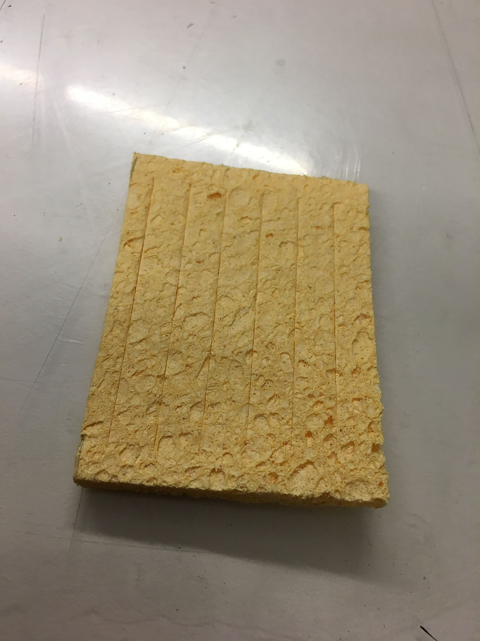
I had to take it a belt sander to bring it down to 0.20-0.25cm.
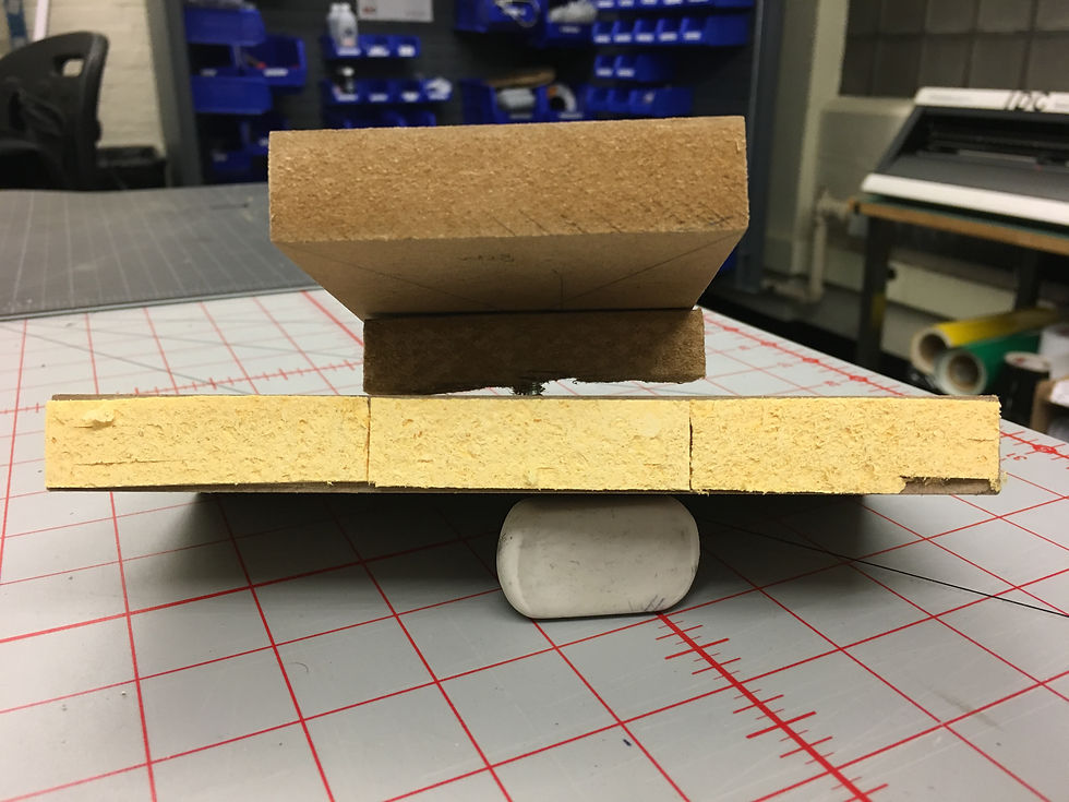
There is almost no side-to-side clearance due to the preload. However, the sliding feels very awkward. I want to try attaching a less stiff material as a preload.
Currently, it looks like:
NOTE TO GRADER
I do not completely understand how to estimate the stiffness of my dry sponge. I will ask for clarification during Monday's recitation. Additionally, I think I have completed bits and pieces of PUPS #5 here and there in my past blogpost. I ask for your patience as I consolidate my work for PUPS #5.
GEEK & SEEK: HORIZONTAL DRILLING
I was talking to a friend who has been working in oil and gas, and he briefly mentioned how drilling can be done many kilometers sideways. That bugged me for a while. I couldn't figure out how a hard metal drill bit, and a long metal drill pipe can be made to turned at a 90 degree angle.

After doing some research online, I found that oil and gas companies mainly uses the Horizontal Directional Boring (HDB) technique. In this technique, the drill bit's direction can be controlled by a drill motor attached behind the bit. The drill motor is able to apply a force onto the rock formation on one side, in order to generate a reaction force to push the drill bit in the opposite way. The drill pipe undergoes plastic deformation, and is surprisingly ductile. The HDB technique is also used to drill tunnels in order to install telecommunication lines and power cables. The following video has a quick explanation of the technique:
As the depth increases, the pressure and temperature increases rapidly. Reportedly, pressures and temperatures can go up to 500K and 40,000 psi. That pressure, according to a lead character in blockbuster movie Deepwater Horizon, is enough to "split a car in half". The drill bit is cooled using either water, or a special chemical mixture, otherwise known as "mud." The fluid is also used to fracture the rock formation for faster penetration by the drill bit. This video illustrates some of the common practices in temperature regulation, and deep sea drilling:
Comments