


2.77 Week 6
- Mar 19, 2017
- 3 min read
This week is mainly spent digesting and creating the error budget spreadsheet. It is a tremendously powerful tool, and I really want to understand how it works.
The error budget is a spreadsheet to help a designer work out the feasibility of his concepts, and to help him evolve them.
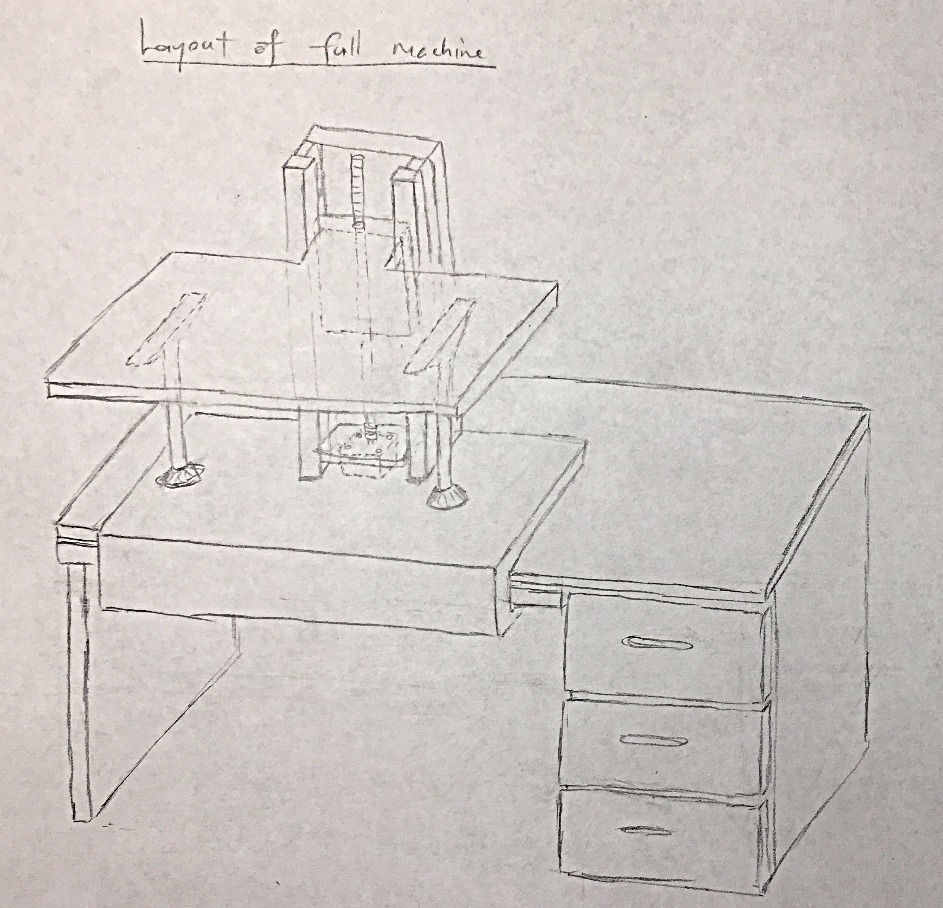
Concept Sketches
In the past few weeks, I was fixated on the telescopic table.
This week I started looking at the manufacturing and assembly risks of creating such a system. The risks and their countermeasures are summarized in the following spreadsheet: Risk and Countermeasures.
The main risk that I have identified with this concept i the telescopic legs. They are hard to find online. Suppliers on Alibaba require a minimum order of 1,000 units. Those that supply single units either only supply foldable legs, or require you to buy the table top as well as the legs. Consequently, I will have to build the legs myself. A concept that I have in mind looks like this:

This design is created by Eurotruss, a German company. The telescopic leg seems to offer a continuous range of heights, as opposed to discrete steps that you have to stop at. However, I will not be able to use this specific component from Eurotruss because the minimum height is 45cm.
As a backup, I looked into scissor linkages. To my surprise, there is a large number of scissor linkage applications for the specific purpose of lifting. This concept was initially overlooked, because of potential user hazards. In particular, people’s hands might get caught between the linkages as the table is actuating upwards. This can actually be prevented by apply soft rubbery attachments around the edges of the linkages.

However, with only one leadscrew, there are severe limitations when it comes to precision in actuation.
This is when I stumbled upon this YouTube video (see below) changed the way I look at scissor linkages. In the video, the vertical movement is incredibly smooth. This really inspired me, and I want to do error budget on this concept, and test it to see if I can obtain the same performance. It will be a very easy procedure. It cannot take more than a few minutes on the laser cutter.

Error Budgets
The next step will be to create the error budgets of my two concepts. First, I have to assign appropriate coordinate systems. The coordinate systems were assigned based on the Point of Interest (POI), and Points of Attachments (POA). The sequence of coordinate system follows the structural loop of the machine, which traces the path of forces acting at the POI on the machine, through the machine, and back to the POI.
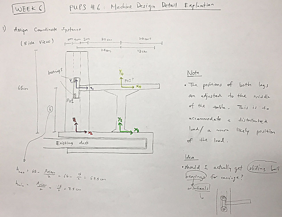

After assigning the coordinate systems, I proceeded to create error budgets for the two concepts. At this point, I still have a bunch of questions on how to use the error budget. To start, I activated 3 coordinate systems: (1) Carriage & Table, (2) Vertical Axis, and (3) Telescopic Leg. I entered the material properties, and the designed dimensions, made changes to the compliance matrices, and finally ensured that I get a reasonable output. The error budget can be found here: Error Budgets. I have also compiled my questions here.
This is an example of the calculations for Coordinate System #2: Vertical Carriage:

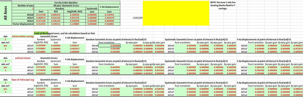
By combining the output of the first 3 Coordinate Systems, I am able to obtain the predicted errors for each axis:
GEEK & SEEK: HOW BURJ KHALIFA MAINTAINS ITS STABILITY IN THE WIND
Tall skyscrapers have a greater risk of oscillating in the wind. Wind speeds are very high when there are no obstructions around the building.
Just like water moving around a pillar in the water. You can notice that directly behind the pillar there are no streamlines. This regions are known as eddies. When the eddies are asymmetrical, the air becomes turbulent. This can cause the building to oscillate back and forth. If the oscillation is at the natural frequency of the building, this will cause the building to oscillate to very large amplitudes, increasing the possibility of sustaining severe structural damage. The scientific term of this phenomena is known as vortex shedding. It is one of the causes proposed for the failure of the Tacoma Narrows Bridge.
To mitigate the effects of vortex shedding, the Burj Khalifa adopted an elegant helical fin design. This design disrupts the fluid flow along the length of the building, thereby preventing vortexes to build up in strength. Similar designs are also adopted in a wide range of settings, from small chimneys to the enormous submerged cylinder of the Perdido Spar, an offshore oil platform.


ANALYSIS
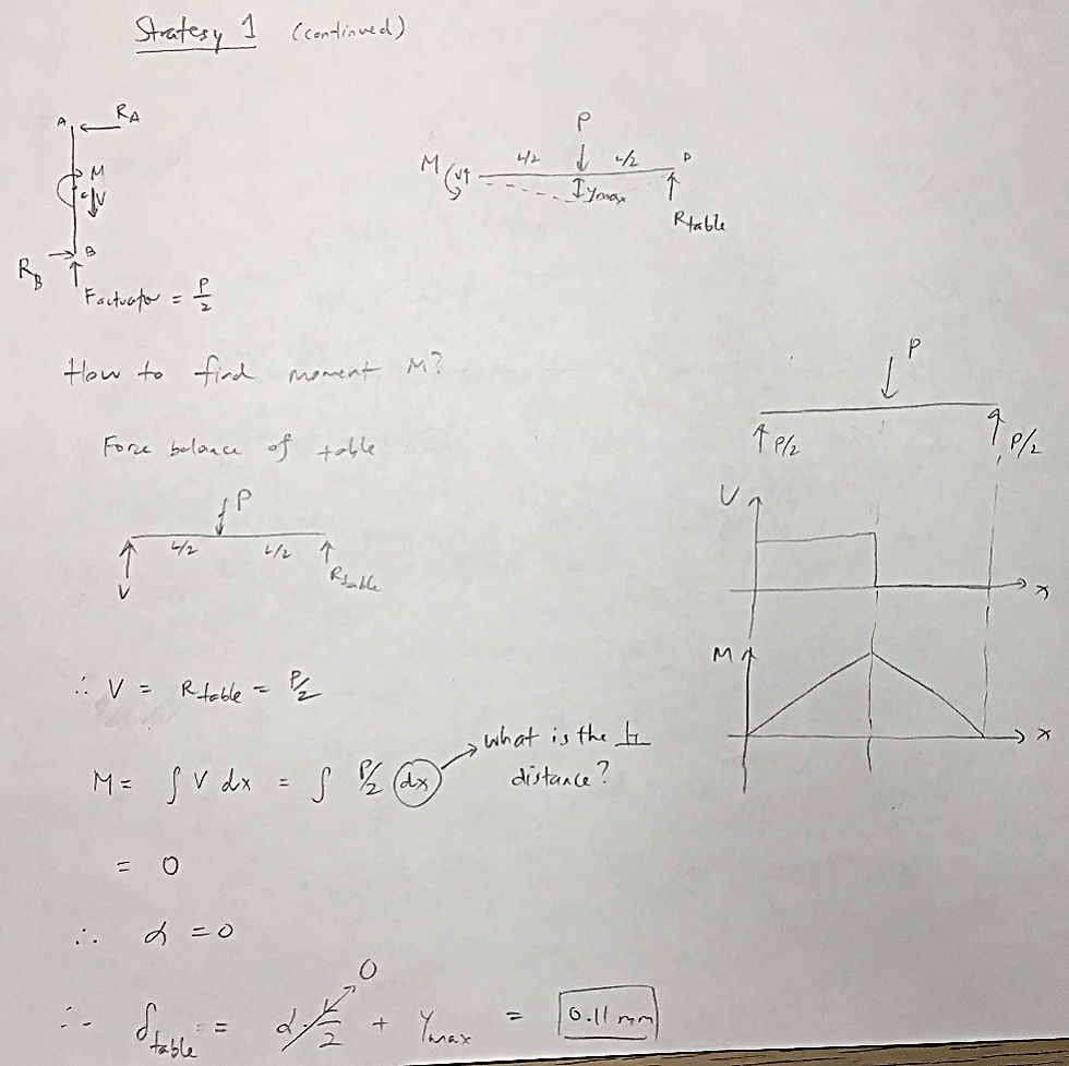
These are some analysis for the telescopic leg concept from last week, and how it compares a cantliever beam.

Comments