


2.77 Week 8
- Apr 9, 2017
- 5 min read
2.77 is gearing up. This week started with me confirming my table concept, and diving head-first into more experimentation and calculations. For easier reading, I have combined my progress in week 7 with my work this week.
INDIVIDUAL PROJECT: HEIGHT ADJUSTABLE TABLE
Background
Before week 6, I was convinced that the telescopic table is the best concept. In week 6, I found that telescopic legs cannot be easily sourced from suppliers in small quantities. This prompted me to look at scissor linkages as an alternative concept. By the end of week 6, I had three different concepts: (1) telescopic table, (2) truss, and (3) scissor linkages. I knew I had to talk this through with someone who knows better. I went to Professor Slocum.
The discussion is a big turning point. Professor Slocum was impressed by the telescopic table concept. The table will be extremely stiff, and will have minimal errors. But he would like to see me take on a more challenging concept, as an exercise to learn how to properly use the error budget spreadsheet. The spreadsheet is a silver bullet when it comes to designing precision systems. As such, I revisited the (defunct) cantilever concept, as well as the truss concept:

Truss Concept
Now let us dive deeper into the truss concept. The Point of Interest (POI) is near the middle of the table. Coordinate System (CS) 1 is allocated at the end of the table, in the middle of the bearings. CS 2 is allocated at the bottom of the rails, and is flushed with the base.
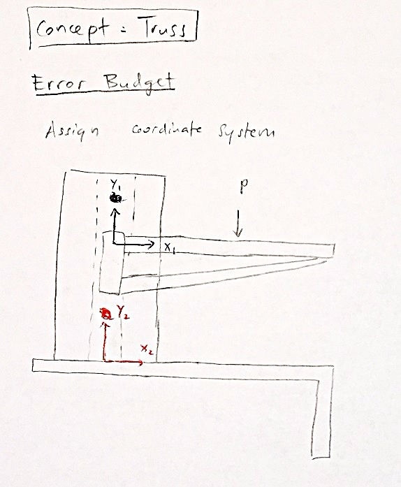
The structure in CS 1 is the truss. It can be approximated as a cantilever beam. The force is applied in the middle of the table.


The bearings at CS1 will be teflon pads. They serve to preload the slider and to reduce the friction between the slider and the rails. The position of the bearings as follows:

To get a better sense of the weight a truss can support. I went down to the gym found a truss that is bolted to the wall. It measures around 30cm by 30cm. I put my weight on it, and it did not even budge. However, I did notice that the point where most of the load is. There is some significant deformation. The drilled hole at the point of loading might have made the deformation even more noticeable.


The structure in CS 2 is the vertical carriage. It can also be approximated as a cantilever beam. I recalculated the compliance matrix, and compared it with my peers to make sure the numbers are in the same order of magnitude.

Structure
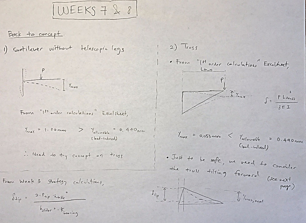
Initially, I explored the concept of having one truss that stretches from the slider all the way to the front of the table. I performed first order calculations on the truss based on load-induced deformation, as well as geometric errors (insert spreadsheet). This first order calculation spreadsheet contains A LOT of calculations for different concepts. It also contains calculations for all components of the height adjustable table:
Structure Concept #1: One Long Truss
("Tapered Cantilever" tab)
Initially, I use one long truss, the length of the table itself. Using the "Tapered Cantilever" calculator, the truss support will experience 0.348mm of error. This will be very close to the allowable load-induced structural error of 0.440mm.

Structure Concept #2: One Mid-length Taper Cantilever
("Tapered Cantilever" tab)
In response to the large error in Structure Concept #1, I decided to reduce the length of the tapered cantilever from 450mm (full length of table) to 240mm (~mid-point of table), and assume that the rest of the table will be infinitely stiff. This gives me a small error of 0.053mm.
The error budget for the entire system is as follows:

This is well within the error allowable calculated using the error apportionment spreadsheet.

Note
Speaking of the error apportionment spreadsheet, I sort to challenge myself, by reducing the total allowable error from 5mm to only 3mm.
Structure Concept #3: Two Mid-length Taper Cantilevers
At the back of my mind, I am worried that the table will not be stable enough to withstand off-centered forces on the table surface. For example, when there are downward force on either side of the table, I can visualize the table tilting sideways. As such, I created a new budget spreadsheet, assuming that I use two shorter trusses, instead of one long one. The errors are indeed smaller.

Attachment (Tabletop & Slider)
(“Attachment_Slider” tab)
I assumed the worst case scenario. Applying a force on the side of the table, while using only one truss. The potential failure modes include the steel screws shearing, or the wood shearing, or the screws pulling through the wood. It turns out that as long as I have 1 or 2 screws, it is enough to prevent the table from snapping off. In my calculations, I had a factor of safety of 3. Next steps will be to include the tilting of the slider, as well as the deformation of the table in the negative y-direction.

Attachment (Rails & Base)
(“Attachment_Base” tab)
A preliminary analysis is worked out in class. I will be looking into that in this coming week. As of now, it will need only 6 screws to hold it together. The potential failure modes analyzed were the steel screws breaking from tension, or the wood shearing, or the screws pulling through the wood.
Actuator
(“Actuator” tab)
In the Q&A session after Monday’s class, we talk about how it is too difficult to put the leadscrew through the entire length of the slider. This means that we will have to tap a shorter separate segment for the leadscrew. Additionally, I have included ball bearings to help guide the leadscrew during actuation. This will prevent the leadscrew from tilting unnecessarily.

I will also be using anti-backlash nuts (they already came in today!). They will serve to preload the leadscrew, in order to prevent backlash during actuation.

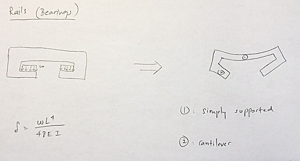
Rails (i.e. Vertical Carriage)
(“Rails” tab)
I have started my preliminary calculations on the rails. Next steps will be to properly model the component and size the dimensions based on desired stiffness.

Bill of Materials
("BOM" tab)
As stated last week, I have already acquired several items online. Among other things, this include the leadscrew, the WAC20 coupling, the anti-backlash nuts, and the leadscrew bearings. I plan to source the wood from shops around campus.
CAD
I have done a project using leadscrews, and the NEMA 17. It should not take me too long to CAD out everything. However, I want my calculations to be more or less solid, before CAD-ing out my parts.
GEEK & SEEK: TOMAHAWK CRUISE MISSILES
Earlier this week, President Trump ordered a missile strike on Syrian airfield Shayrat, in response to a chemical weapons attack launched by the Syrian government days earlier. 59 Tomahawk cruise missiles were launched from two American destroyers in the Mediterranean Sea. These missiles flew over a range of 200km at 800km/h and hit their targets straight-on. These bunker-penetrating missiles completely destroyed the airfield.

The design of the tomahawk cruise missile is ingenious. For the first stage of its flight, the Tomahawk uses a solid rocket boosters running on Aluminum fuel for the initial thrust. After a minute or so, the booster rocket disengages, and the cruise control takes over. Wings unfold from the fuselage and the turbojet engine takes over to carry the missile over the remainder of its journey. GPS guidance is used to guide the missile to its target. The TERCOM, previously DSMAC, compares the preloaded terrain contour with measurements made during flight by an on-board radar.

The development of the Tomahawk has its roots in the German V-1 rocket, and the American Kettering Bug. The following video does a great introduction to the history and truly remarkable technologies behind the Tomahawk:
Comments