


Final Calculations
- May 20, 2017
- 4 min read
Road-map
I just want to recap the path that I have taken thus far. First, I started off determining the functional requirements of the table that I wanted to build. Second, I experimented with the error apportionment spreadsheet to determine the precision that I want in my system. Third, I developed strategies and concepts for my height adjustable table. Fourth, I did first order calculations of my concepts to do a sanity check. Fifth, I developed my error budget to see if my first order calculations are correct. Sixth, I purchased my materials and developed countermeasures for any potential risks. Seventh, I proceeded with measurements, detailed CAD, and simulation. Finally, I built, assembled and tested my table.

In truth, this road-map is not a linear path. Depending on the amount of raw materials available and whether or not I managed to hit the manufacturing tolerances, I went back and forth from calculations to CAD to building my table. These iterations were made keeping my functional requirements and the concepts of precision machine design in mind.
Bill of Materials
In the beginning of this project, I set a budget of $50 for myself to build this table. This seems like a ridiculously low budget for a table that you will otherwise get for $500-2000 on the market. But guess what, at the end of it all, I had only spent $32, of which $12 on the leadscrew linear motion system and $20 on the Protoneer CNC Shield. All of the Baltic Birch plywood, wood screws, motor, steel brackets, aluminum stock, and many other components have been sourced from the recycleries of a number of MIT shops. The shops include the International Design Center, the MIT Museum Lab Space, the Hobby Shop, and even MIT Media Lab. At no point in this project was I hacking together my table. I had obtained all my materials way before building. There are naturally hiccups in the form of manufacturing errors, and design oversight, but every single time I would go back to my calculations, tweak them, and search for the most suitable solution.
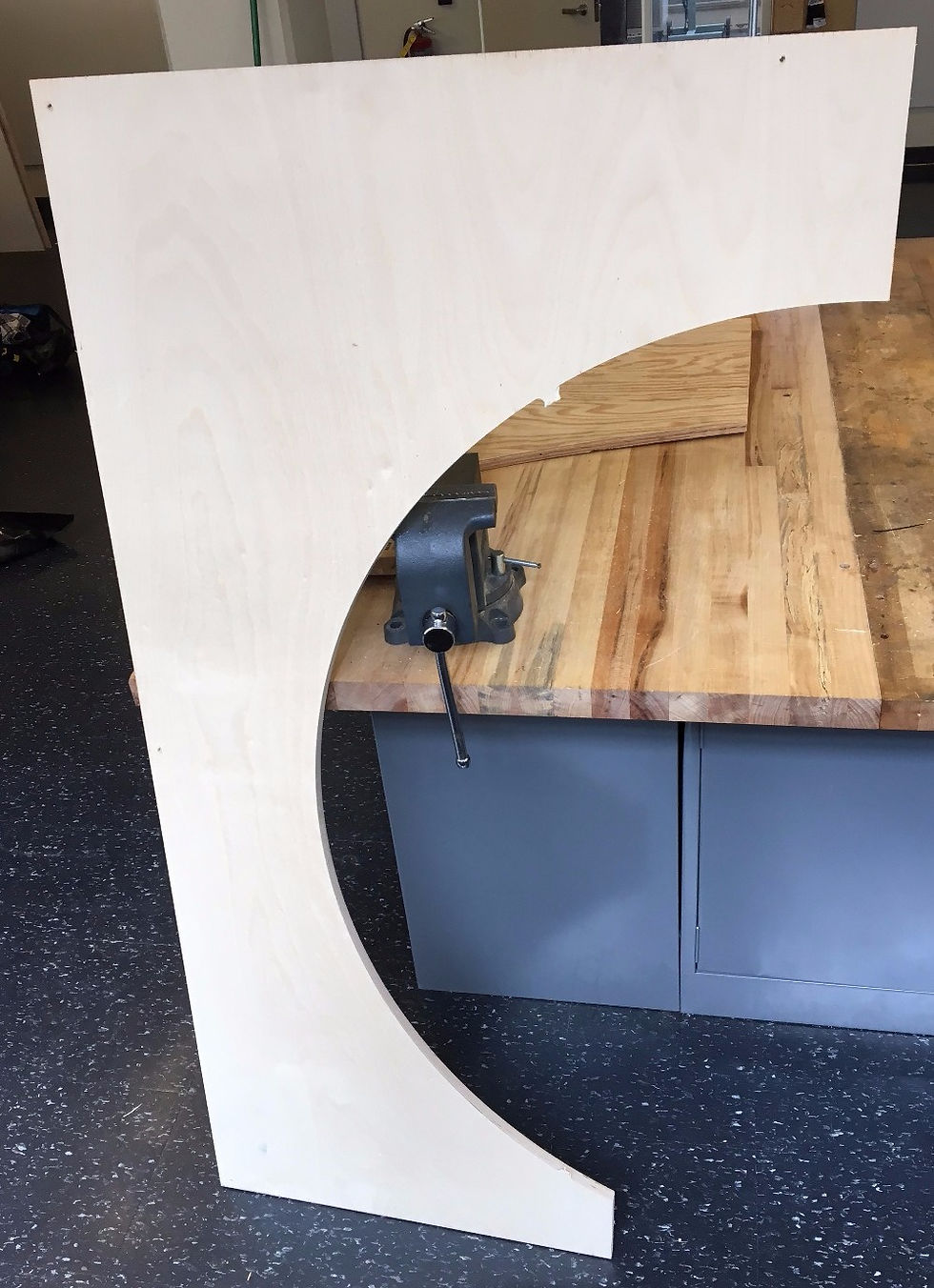
As an example, this is the remnants of a 4' by 8' by 3/4" thick Baltic Birch plywood that I used to build my rails+slider+truss subassembly:
Design decisions
Dimension of keeper rails will be dictated by St Venant's Principle:
No preload of slider. Gap between slider and side of rails is only 0.25mm. The angular deflection will only by 0.17 degrees. This is within my design requirement. The challenge will be actually maintaining such a small gap uniformly down across the entire length of the rails.
No need for preloading leadscrew nut assembly. Since table is always pushing down on the leadscrew, the weight of the leadscrew will provide the preload (i.e. preload by gravity).
Including steel angle brackets and Al backplate to join my subassemblies. I brought my CAD to Hayami from Hobby Shop, and he pointed that I need to support my rails better. I went back and calculated the moment at the base of my rails.
This is obviously a simplification, because the glue is applied over an area. However, I do know that from watching YouTube videos of people who have empirically determined the strength of the wood glue that a glue joint will definitely not withstand this load.As such, I included steel angle brackets at the pivot to resist the moment. But this is insufficient, because the brackets are not at perfect right-angles. As such, I added an Al backplate to ensure my rails and base are attached firmly together.
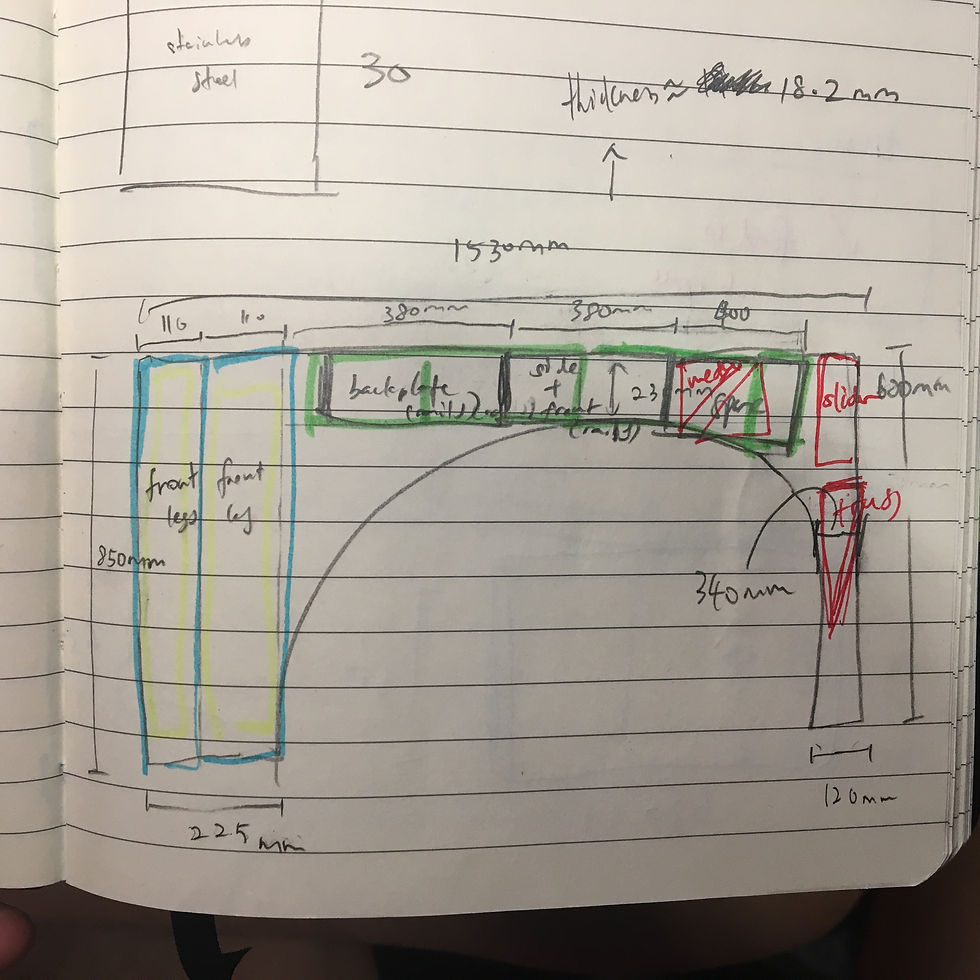
Changed flat base to base with "legs". In my previous design, the rails fit directly onto a flat piece of wood. This means that the motor will have to fit in between the keeper rails. However, given the thickness of my rails, this is going to be an unnecessary engineering challenge. As such, I made the decision to shorten my rails. By shortening the rails, I am able to: (i) Minimize running parallelism error on my rails. (ii) Make whole structure more lightweight. In its place, I decided to use "legs." These legs are either front facing (i.e. improve second moment of inertia in y), or side facing (i.e. improve second moment of inertia in z).

Final Calculations
By this time I had more or less confirmed my calculations. But as I discovered new building materials around campus, I was inspired to change my design to make it more robust, and easier to build. Professor Slocum, Hobby Shop mentors, and my peers also gave me some pointers to look out for. As such, it is necessary to update you on the changes in three main areas:
Axis Error Apportionment Estimator
1st Order Calculations & Sizing
Error Budget
My changes to the Axis Error Apportionment Estimator include:
Change length of leadscrew from 600mm to 400mm. I re-measured my current desk’s dimensions, and there is no need for my desk to go beyond a height of 600mm.
After playing around with the dimensions of my desk and rails on the Error Apportionment spreadsheet, I finalized the length of my slider to be 170mm. I catered for a small gap of 0.25mm between slider and either side of rails.
My changes to the 1st Order Calculations include:
[Actuator Tab] Given my leadscrew, and my NEMA 17 stepper motor, I found that when the motor has a 30% efficiency, the force provided by the actuator is 424N. In a bid to challenge myself, I decided to increase the load on my tabletop to 300N. As such, the forces that my actuator has to act against are: weight of tabletop + truss (~40N), applied load (300N), and friction (~80N).
[Attachment Tabs] Based on the screw size, and the screw's engagement length, I spec-ed out the number of screws needed at each point of attachment.
After re-measuring my current desk, I decided to increase the length of my tabletop from 450mm to 500mm, so that it will fit both my laptop and books.
My changes to the Error Budget include:
Adding the 3rd and 4th coordinate systems
The final error budget looks like:


Comments